IoT Projects: The ESP8266
January 15, 2020 | #esp8266 | #iot
My first dive into the IoT world!
My wife recently asked me about purchasing an automated pet-feeder for Kneesox, our Cornish Rex cat. After doing some initial research I quickly realized that most feeders, which retail for upwards of $150 USD, are primarily composed of simple servos and a timer mechanism.
After some quick research and a trip to GitHub, I learned about a cheap $5 USD micro-controller which could power a variety of general purpose input-output devices AND with the added benefit of having WiFi on the chip!
My repository, nodemcu-iot-starter-kit is a few demos showing how to get started with this micro-controller. Naturally, there were a few steps I needed to take to get my development environment setup to work on this device.
Lesson 0 - Install the ESP8266 Board Package and the Serial Port Driver
So what I realized quickly is that the ESP8266 that I purchased comes pre-flashed with a Lua interpreter onboard. Almost all tutorials are telling me that we should go ahead and flash it so we can use the Arduino IDE.
NOTE: This action is writing directly to the firmware, erasing the NodeMCU firmware. We can always flash it back to the old Lua SDK if we want.
Instructions are located here.
- I spent a few minutes determining what drivers to download. I've gone ahead and placed them into the
/driversdirectory. When you unzip this, just run the.exeinstaller. - The Arduino IDE looks like it can be built or downloaded via the Windows 10 store.
- Connect your NodeMCU to the Computer
- Install the COM/Serial port driver
- Install the Arduino IDE 1.6.4 or greater
-
Install the ESP8266 Board Package
- Enter
http://arduino.esp8266.com/stable/package_esp8266com_index.jsoninto Additional Board Manager URLs field in the Arduino v1.6.4+ preferences (Open Arduino IDE–>File–>Preferences–>Settings).
- Enter
Step 4 is where we actually flash the controller with the new board package. This was done using the Board Manager feature of the Arduino IDE.
Once everything was setup, I simply followed the rest of the instructions which have us print out the infamous Hello World! prompt via our micro-controller.
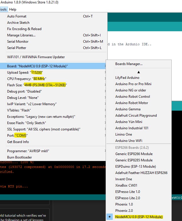
To do this, open up Arduino IDE and set the following config values
- CPU Frequency:
80MHz - Flash Size:
4MB(FS: 3MB OTA: ~512KB) - Upload Speed:
115200 - Port: Select your Port - mine was
COM3

Once you have this setup you'll be on your way to flashing the ESP8266 with your arbitrary code.
Lesson 1 - Hello World
Hello World is pretty easy on this controller, the code is located in /lessons/1-hello-world.
void setup() {
  // put your setup code here, to run once:
  // Configure the serial baud rate to be the same as whats configured in the Ardunio IDE..
  Serial.begin(115200);
}

void loop() {
  // put your main code here, to run repeatedly:
  Serial.println("Hello world!");
  delay(5000); // delay for 5s
}
Although small, this is actually really cool to see in action. The next thing I worked on was blinking an LED that came with my starter kit.
Lesson 2 - Blinking an LED
The first task was to blink the onboard LED. To do this, we just have to set pin D1 to OUTPUT mode, then in our main loop, then toggle this from HIGH to LOW to represent on and off.
I found the tutorial doesn't really explain the constants being used in the lib, so a quick google search led me to the official Arduino reference!
https://www.arduino.cc/reference/en/language/variables/constants/constants/
The context of HIGH and LOW depends on whether or not you have your pin set to INPUT or OUTPUT
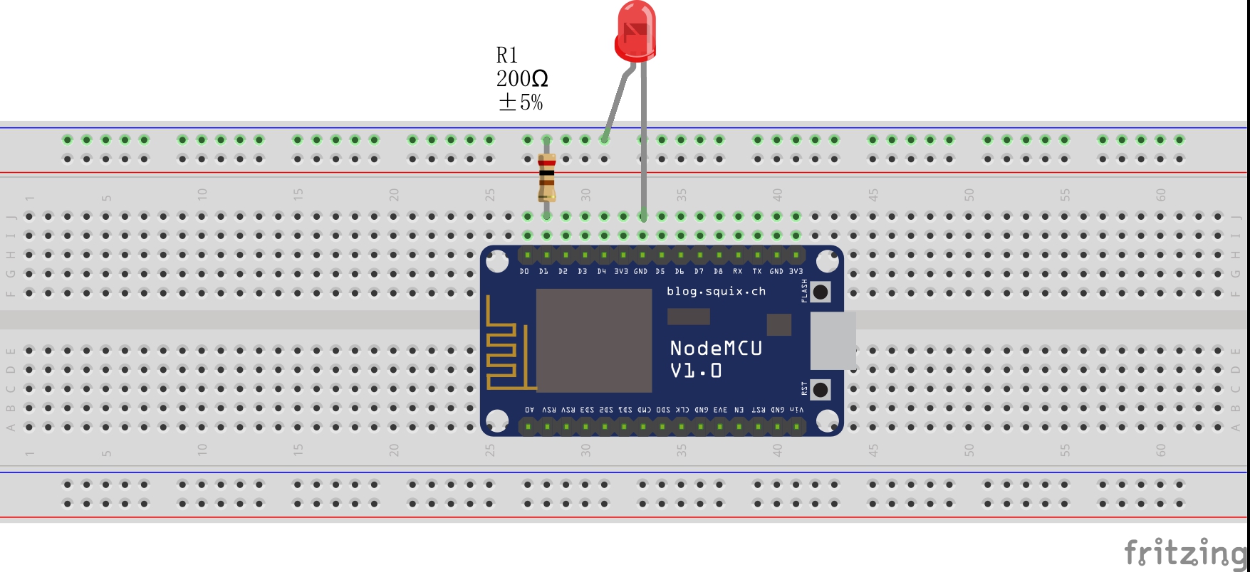
2A - Blinking an external LED

Although this post isn't intended to be any type of exhaustive guide, I will have subsequent posts containing more detailed guides as well as documentation on my automated pet feeder project!